Installing AuCountry Jaguar Cowl on my AA5-B
This page is to document the steps I am taking in the process of installation of Jaguar Cowl.
The cowling is available from AuCountry Aviation - www.aucountry.com.
Hardware
The Cowling comes with the Installation Instructions which have a list of Tools and Harware reqirements, but I still had to spend many hours fuguring out exactly where to buy parts, how many and what exact sizes to order.
The following web sites helped me to figure it out:
http://bobmay.astronomy.net/misc/drillchart.htm - helpes to figure out the numbered drill bit sizes in relation to fractional rivet sizes.
http://www.hansonrivet.com/w06.htm - solid rivet installation guide. I haven't worked with solid rivets before. Notice suggested Clinch Allowance at the bottom of the chart. It helps to determine the proper rivet length.
http://www.afscamloc.net/xua/downloads/4002%20Series.pdf - CamLoc selection and installation instructions.
Here is my parts list(to complement, not replace the list in the Instructions):
- Rivets to attach the upper cowl halves to the hinge - cherry-max countersunk head 1/8". 38 rivets - 19 on each side. Install manual asks for CR3212-4-2. According to Aircraft spruce <https://www.aircraftspruce.com/catalog/hapages/cherrymax.php> those have grip range 0.63 to .125. I measured hinge thickness + upper cowl thickness = 0.142". Maybe CR3212-4-3 is better? Ordered CR3212-4-2 anyway. Those require drill #30, Aircraft Spruce part 12-04217 and #30 countersink, Aircraft Spruce part 12-00880. The cage for countersinks is Spruce part 12-00940.
- Nutplates to hold lower cowling halves together. 9 on the bottom + 3 on top. There are also 2 to hold upper cowling halves to lower cowling and 2 more to hold the hinge to the lower cowling. Total 16. Install manual asks for MS21048-L-08. I believe Manual says 'countersunk' by mistake. I found those on www.cessnadirect.com. AircraftSpruce has MS21047L08 which looks identical to MS21048-L-08, but Gary explained that MS21047L08 will rust and MS21048-L-08 will not.
- Solid rivets to attach those nutplates to joggle, countersunk 3/32". The lower cowl joggle thickness measures between 0.07 and 0.09", the nutplate thickness is 0.035", so the total grip is between 0.105 and 0.125. The clench allowance for 3/32" is 0.094. So need Aircraft Spruce part AN426AD-3-3.5. Minimum order is 1/8 lb - a lot of extra rivets. Require drill #40, Aircraft spruce part 12-04214 and #40 countersink part 12-00881. To attach 2 nutplates for hinge attachment, need Spruce part AN426AD-3-5 as the cowl thickness there measures 0.157 and 0.197 for the total rivet length of 0.286 and 0.326
- Camloc part according to Install Instructions, except they leave out the Camloc receptacles, Aircraft Spruce part 214-16N. Those receptacles require 1/8" rivets. The receptacle plate depth is 0.091, the lower cowl joggle thickness is between 0.114 and 0.134, the 1/8" rivet clinch allowance is .094, so total rivet length between 0.3 and 0.32. Ordered Aircraft Spruce part AN426AD-4-5. Also need Camloc pliers, Spruce part 12-01475, although I used a cut split washer and Cleco pliers instead. According to installation instructions(link above) you need 12mm drill bit for the gromet and 16mm drill bit for the receptacle. I got brad point bits from Amazon - http://www.amazon.com/gp/product/B001DT2ZTG - they make fairly smooth holes in fiberglass.
- Rivet Squeezer, Aircraft Spruce part 12-01462, and two squeezer dies part 12-01466.
- Clecos, Spruce part 12-01138. 12 to hold lower cowl halves together, 19 to hold the upper cowl halves to the hinge and 10 to hold the upper halves to lower cowl - 31 all together. Cleco pliers, Spruce part 12-10105.
- Engine hoist, if you will need to adjust the engine alignment. I borrowed one. Torque wrench to torque the engine mounts to 40 ft-lb. I got one on Amazon: http://www.amazon.com/gp/product/B0028081GK (Gorilla Automotive TW605 Torque Wrench)
- Lever to remove the nose strut unless you are prepared to cut off the nose strut fairing boot. I borrowed one and later made my own because the borrowed one was too loose. See instructions here: http://www.bondline.org/wiki/Nose_Strut . Zinc chromate primer - to put the strut back. I orderd one from Fletchair and got a zinc phosphate primer instead. Hope it works the same way.
- Two 1 inch bolts with the same thread as propeller bolts - to hold the spinner backplate in place while fitting the cowl. From local hardware store.
- to be continued.
Pre-installation Engine Alignment
I have just installed a Ly-Con overhauled engine with the new Lord engine mounts with one spacer on each mount. Before installing the Jaguar cowl I am checking the fit against the original cowl. The old bottom Lord mounts were leaking and the spinner was sagging agains the nose bowl. Now the spinner is hanging a little high and a little to the right - see pictures.
-
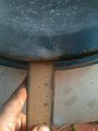 Bottm
-
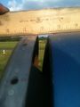 Top
-
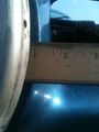 Pilot side
-
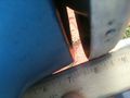 Passenger side


Not sure how to go about engine alignment I asked for help on Team Grumman. Bob and Gary helped with advice but they didn't quite agree with each other.
Bob: \"...The method we used before Gary sent out his cowl was to align the spinner with the factory cowling, leaving it perhaps 3/8" high with new mounts, as they sag with age, and in a few months they'd be allowing the spinner to align very closely with the nose bowl. Some argue that the engine will rise up when in flight and pulling against the mount, and it will overcome the sagging in the rubber mounts. This is damned hard to measure in flight. <G> ...\" Full text of Bob's e-mail at the end of the page
Gary's experience is that engine mounts don't necessarily sag with time and that engine rises agains the cowl in flight. Here is Gary's e-mail: http://forums.matronics.com/viewtopic.php?t=81902
I decided to take a middle road - leave the vertical alignment as is and center the Jaguar cowl vertically with the spinner back plate.
A few days later I figured I don't need a $200 digital level to check the engine vertical angle. My iPhone has an accelerometer and a quick app search confirmed - there is a digital level app, and it's even free!
http://www.ihandysoft.com/level_free.html
Here is the result:
-
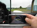 Calibrating - no plane leveling needed, just press -calibrate-
-
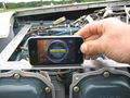 Measuring engine angle


So my engine is pointing half a degree up. Should I start worrying?
However I was more concerned with horizontal alignment. As Bob's e-mail at the bottom of this page suggests, there is no direct way to measure the horizontal alignment. The consensus seems to be that the original cowl is the best available reference point. I vaguely remembered that I sometimes I had to hold a little left rudder in cruise, so I added one spacer on the top right mount and one spacer on the bottom right mount. This over-corrected the alignment, but ony a tiny little bit. Maybe I should have used half-thickness spacers, but I don't have any right now. If I will end up holding the right rudder in cruise, I will replace full with half-thickness, but for now I will just align the Jaguar cowl a little tiny bit to the right of the spinner, in case I have to go to half-thickness spacers on the right.
First Fitting
Install instructions don't mention this, but you have to remove the nose strut fairing boot. If you don't want to cut it off, you will have to remove the nose strut.
Here is the first fitting. The cowl lined up nicely. Only 2 bolt holes are drilled and no trimming yet. The install manual calls for 3/16 drill for screw holes, I am using the 5/32. This gives me a tight fit and a little more room for error.
To hold the cowling in place I cut a couple of wooden planks to size and jammed them under the bottom corners by the firewall - see pictures.
In the process of trimming I had to remove and re-install the bottom halves several times. I found it easier to remove the halves clecoed together as one piece instead of removing 12 clecoes every time. I had no exhaust, no nose strut and before removing the cowl I would remove the spinner back plate which was held by two 1 inch bolts from hadware store and would screw one of those bolts back to make sure the flywheel would stay in place.
-
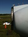 Side View
-
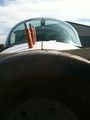 Top
-
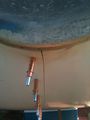 Bottom
-
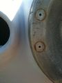 Passenger side
-
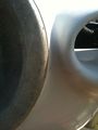 Pilot Side
-
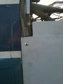 Top Right Corner
-
 Top Left Corner
-
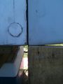 Bottom Right Corner
-
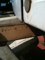 Bottom Left Corner


The last picture - Bottom Left Corner - gave me a little worry at first - the cowl seemed alomst 1/2 inch wider then the fuselage. But this gap dissapeared after I put in the bottom side corner screws.
Trimming and drilling screw holes
As I mentioned, I am using the 5/32 drill bit for screw holes - works well for me.
I ended up enlarging a couple of screw holes for a correct fit, but they are still covered completely by the button head screws so I am not worried. Just in case, I asked Gary for epoxy repair materials and instructions and here is his answer: http://forums.matronics.com/viewtopic.php?t=82085
Installation instructions recommend using Dremel for trimming so I bought a Dremel. Not needed. I did all trimming with my dry wall sanding block and a pack of 100 dry wall sand paper. Fresh sand paper goes thru the fiberglass like a knife thru butter and you have less chance to screw up and cut too much.
On the Pilot side I ended up trimming to Gary's trim line but on the Passenger side I hardly had to trim at all.
Cutting a hole for PowerFlow exhaust
The Cowl instructions don't cover this. I guess, this means that one should follow the PowerFlow instructions for cutting the hole. The template in PowerFlow instructions shows a semi-oval hole, and on another page it shows how to make a removable "door" between that hole and firewall to make cowl removal easier.
Question to current PowerFlow owners: How difficult it is to remove the standard cowl without that "door"?
As for Jaguar cowl, turns out, it is impossible to remove the right bottom cowl if you have just an oval hole and want to keep the muffler in place. I checked with Gary and he said he just extends the hole to the firewall and puts an extra nutplate to replace the one that is wasted. I have an aversion to cutting so I came up with an alternate method. I figured I could just remove the PowerFlow muffler instead. It takes me 2 minutes to remove 3 bolts on the muffler ball joint and 1 bolt on the support arm, and 3 minutes to put it all back. The cotter pins will be a pain, though. I wonder if there are easy-on easy-off cotter pints, like a safety pin, or something?
Dremel proved itself useful.
To avoid cutting too big of a hole, I disconnected the muffler and cut the hole just big enough to fit the muffler through - see picures. Then I started enlarging it gradually with Dremel filing drum as I was trying to align the muffler with the intermediate pipe. Took a long time - about 4 hours, but the hole came up pretty close to what I wanted, except maybe in one spot the gap is a little larger.
-
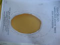 First Cut compared with PowerFlow Template
-
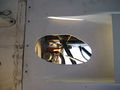 Final Cut, should have been perfectly oval


Cutting a hole for Landing Light
Another item not covered in the install instructions. Gary provided the line to cut but in e-mails he first said that the line on my cowl is off by 1/4", then he said it wasn't my cowl, but another guys cowl, and mine has the line in the right place. Just to be safe I left a 1/2 inch safety margin and cut a much smaller hole at first. Then I put the cowl on the plane and tried to find the best fit. Gary mentioned that there is very little space between the light and the starter, but I got a Sky-Tec starter and there was enough space between starter, but very little space between the PowerFlow 4 to 1 collector, so I had to move the light housing forward a little from Gary's line. I hope I can still aim the light somewhere in the vicinity of runway! Then I cut a couple of 1/8 holes and clecoed the housing to the cowl, removed the light, drew the outline of the housing on the cowl from inside the housing and cut along the line. My hole ended up pretty close to Gary's line, but it is a bit wider and a bit shorter.
Camlocks on the leading edge of the top cowl
Installation instructions call for a screw and a nutplate on the leading edge of the top cowl because the standard camlock receptacle sticks out too far into the cooling air stream, but with Gary’s permissions I installed a camlock. I did find a guy in Belgium who offered to sell me 2 low profile camlock receptacles for $25 each, but I figured that’s too much, and made a couple of my own receptacles which work well with the shortest camlock I could find.
<gallery>
File:First LeadingEdgeCamlock.jpg | Camlock on the leading edge of the top cowl