Installing AuCountry Jaguar Cowl on my AA5-B
This page is to document the steps I am taking in the process of installation of Jaguar Cowl.
The cowling is available from AuCountry Aviation - www.aucountry.com.
Hardware
The Cowling comes with the Installation Instructions which have a list of Tools and Harware reqirements, but I still had to spend many hours fuguring out exactly where to buy parts, how many and what exact sizes to order.
The following web sites helped me to figure it out:
http://bobmay.astronomy.net/misc/drillchart.htm - helpes to figure out the numbered drill bit sizes in relation to fractional rivet sizes.
http://www.hansonrivet.com/w06.htm - solid rivet installation guide. I haven't worked with solid rivets before. Notice suggested Clinch Allowance at the bottom of the chart. It helps to determine the proper rivet length.
http://www.afscamloc.net/xua/downloads/4002%20Series.pdf - CamLoc selection and installation instructions.
Here is my parts list(to complement, not replace the list in the Instructions):
- Rivets to attach the upper cowl halves to the hinge - cherry-max countersunk head 1/8". 38 rivets - 19 on each side. Install manual asks for CR3212-4-2. According to Aircraft spruce <https://www.aircraftspruce.com/catalog/hapages/cherrymax.php> those have grip range 0.63 to .125. I measured hinge thickness + upper cowl thickness = 0.142". Maybe CR3212-4-3 is better? Ordered CR3212-4-2 anyway. Those require drill #30, Aircraft Spruce part 12-04217 and #30 countersink, Aircraft Spruce part 12-00880. The cage for countersinks is Spruce part 12-00940.
- Nutplates to hold lower cowling halves together. 9 on the bottom + 3 on top. There are also 2 to hold upper cowling halves to lower cowling. Total 14. Install manual asks for MS21048-L-08. I believe Manual says 'countersunk' by mistake. I found those on www.cessnadirect.com. AircraftSpruce has MS21047L08. Aren't they the same?
- Solid rivets to attach those nutplates, countersunk 3/26". The lower cowl joggle thickness measures between 0.07 and 0.09", the nutplate thickness is 0.035", so the total grip is between 0.105 and 0.125. The clench allowance for 3/32" is 0.094. So need Aircraft Spruce part AN426AD-3-3.5. Ordered 1/8 lb - a lot of rivets to practice on scrap aluminum. Require drill #40, Aircraft spruce part 12-04214 and #40 countersink part 12-00881.
- Camloc part according to Install Instructions, except they leave out the Camloc receptacles, Aircraft Spruce part 214-16N. Those receptacles require 1/8" rivets. The receptacle plate depth is 0.091, the lower cowl joggle thickness is between 0.114 and 0.134, the 1/8" rivet clinch allowance is .094, so total rivet length between 0.3 and 0.32. Ordered Aircraft Spruce part AN426AD-4-5. Also need Camloc pliers, Spruce part 12-01475, although I used a cut split washer and Cleco pliers instead.
- Rivet Squeezer, Aircraft Spruce part 12-01462, and two squeezer dies part 12-01466.
- Clecos, Spruce part 12-01138. 12 to hold lower cowl halves together, 19 to hold the upper cowl halves to the hinge and 10 to hold the upper halves to lower cowl - 31 all together. Cleco pliers, Spruce part 12-10105.
- Engine hoist, if you will need to adjust the engine alignment. I borrowed one. Torque wrench to torque the engine mounts to 40 ft-lb. I got one on Amazon: http://www.amazon.com/gp/product/B0028081GK (Gorilla Automotive TW605 Torque Wrench)
- Lever to remove the nose strut unless you are prepared to cut off the nose strut fairing boot. I borrowed one and later made my own because the borrowed one was too loose. See instructions here: http://www.bondline.org/wiki/Nose_Strut . Zinc chromate primer - to put the strut back. I orderd one from Fletchair and got a zinc phosphate primer instead. Hope it works the same way.
- to be continued.
Pre-installation Engine Alignment
I have just installed a Ly-Con overhauled engine with the new Lord engine mounts with one spacer on each mount. Before installing the Jaguar cowl I am checking the fit against the original cowl. The old bottom Lord mounts were leaking and the spinner was sagging agains the nose bowl. Now the spinner is hanging a little high and a little to the right - see pictures.
-
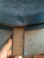 Bottm
-
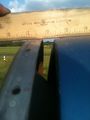 Top
-
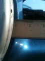 Pilot side
-
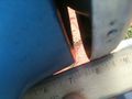 Passenger side


Not sure how to go about engine alignment I asked for help on Team Grumman. Bob and Gary heped with advice but they didn't quite agree with each other.
Bob: \"...The method we used before Gary sent out his cowl was to align the spinner with the factory cowling, leaving it perhaps 3/8" high with new mounts, as they sag with age, and in a few months they'd be allowing the spinner to align very closely with the nose bowl. Some argue that the engine will rise up when in flight and pulling against the mount, and it will overcome the sagging in the rubber mounts. This is damned hard to measure in flight. <G> ...\" Full text of Bob's e-mail at the end of the page
Gary's experience is that engine mounts don't necessarily sag with time and that engine rises agains the cowl in flight. Here is Gary's e-mail: http://forums.matronics.com/viewtopic.php?t=81902
I decided to take a middle road - leave the vertical alignment as is and center the Jaguar cowl vertically with the spinner back plate.
However I was more concerned with horizontal alignment. As Bob's e-mail at the bottom of this page suggests, there is no direct way to measure the horizontal alignment. The consensus seems to be that the original cowl is the best available reference point. I vaguely remembered that I sometimes I had to hold a little left rudder in cruise, so I added one spacer on the top right mount and one spacer on the bottom right mount. This over-corrected the alignment, but ony a tiny little bit. Maybe I should have used half-thickness spacers, but I don't have any right now. If I will end up holding the right rudder in cruise, I will replace full with half-thickness, but for now I will just align the Jaguar cowl a little tiny bit to the right of the spinner, in case I have to go to half-thickness spacers on the right.
First Fitting
Install instructions don't mention this, but you have to remove the nose strut fairing boot. If you don't want to cut it off, you will have to remove the nose strut.
Here is the first fitting. The cowl lined up nicely. Only 2 bolt holes are drilled and no trimming yet. The install manual calls for 3/16 drill for screw holes, I am using the 5/32. This gives me a tight fit and a little more room for error.
-
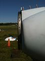 Side View
-
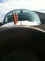 Bottom
-
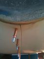 Bottom
-
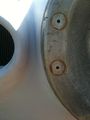 Passenger side
-
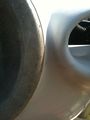 Pilot Side
-
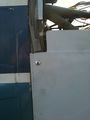 Top Right Corner
-
 Top Left Corner
-
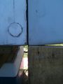 Bottom Right Corner
-
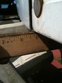 Bottom Left Corner


The last picture - Bottom Left Corner - gave me a little worry at first - the cowl seemed alomst 1/2 inch wider then the fuselage. But this gap dissapeared after I put in the bottom side corner screws.
Trimming and drilling screw holes
As I mentioned, I am using the 5/32 drill bit for screw holes - works well for me.
I ended up enlarging a couple of screw holes for a correct fit, but they are still covered completely by the button head screws so I am not worried. Just in case, I asked Gary for instructions about epoxy repair instructions and materials and here is his answer: http://forums.matronics.com/viewtopic.php?t=82085
Installation instructions recommend trimming with Dremel so I bought a Dremel. Not needed. I did all trimming with my dry wall sanding block and a pack of 100 dry wall sand paper. Fresh sand paper goes thru the fiberglass like a knife thru butter and you have less chance to screw up and cut too much.
I ended up trimming on the left side to Gary's trim line but on the right side I hardly had to trim at all.
After installing the bootom corner screws the gap at the bottom corners dissapeared,
However now the nose strut shock absorbers are riding on the Jaguar cowl fiberglass nose strut fairing. I expected there to be some gap but now there is no gap at all. Question to Gary - did you have this problem in earlier installs? How did you deal with this?
Full Text of Bob's e-mail regarding the engine thrust angle alignment:
START QUOTE
\>Please take a look. I wonder if you could please help me regarding the spacers on engine mounts. I just bought a set of new Lord engine mounts. The old bottom ones were leaking and the spinner was sagging about 1/2 inch against the nose bowl rim. Now I have placed 1 spacer on each(as it was before) and torqued it per manual, 40 lb-feet. Before fitting the new cowl I tried the old one to check and found that engine is now hanging a little high against the nose bowl and a little to the right.
The method we used before Gary sent out his cowl was to align the spinner with the factory cowling, leaving it perhaps 3/8" high with new mounts, as they sag with age, and in a few months they'd be allowing the spinner to align very closely with the nose bowl. Some argue that the engine will rise up when in flight and pulling against the mount, and it will overcome the sagging in the rubber mounts. This is damned hard to measure in flight. <G> Some photographic evidence may be the source of this contention.
It is required to have 1 full thickness spacer between each lower mount and the engine case. It has to do with clearance of the large mount cups from the engine. This isn't an issue with the Cheetah/Traveler with its smaller cups. Any additional spacers on any of the 4 mount points are optional and "as required" to center the spinner.
Lord makes, though they are hard to find, 1/2 thickness spacers, which can be used to jack the engine around as needed to center the spinner better than a full thickness one might. I've had them made from AN970-7 washers on occasion when my supply of the Lord half thickness spacers ran out. Any machine shop with a surface grinder can make you some. Etch and prime before installing.
> My question is - should I try to add spacers to align the spinner to the old cowl before I fit the new cowl, and if you think I should, then why? In other words, why aligning to the old cowl would give me a better thrust angle then relying on the angle provided by the engine mount together with the set of new properly torqued Lord mounts?
In theory the cowling was built on a jig at the factory and the firewall (Station 50) is the reference for all measurements on the plane, so the jigged cowl mated to the firewall by Grumman would give the proper relationship to the nose bowl opening.
Gary says his measurements of the engines, when shimmed to align the nose bowl and spinner, are all over the place with respect to the Thrust Angle of the engine (reputed to be 3 degrees down). I've just used the maintenance manual method in the past, and trusted that the factory jigs were accurate.
If you can determine an accurate reference point (canopy rails are used to level the fuselage fore-aft and laterally), you could begin to measure the actual Thrust Angle of your engine and play with aligning it differently than the Maintenance Manual method suggests. Caution is suggested here, as we are REQUIRED by FAR 43.13 to use the Maintenance Manual methods and tools. If Gary's instructions specifically instruct you to alter the engine Thrust Angle, you can claim that the STC then supercedes the 43.13 requirement. However Gary's anecdotal evidence of differences in various planes, and his discussion on TeamGrumman is not an FAA approved source of data. The factory had good reason to set the engine Thrust Angle down and to the side, and changing it will alter the flying characteristics, possibly in a way that is undesirable, and even unsafe.
> I guess the left/right angle could be checked by measuring the distance from propeller tips to wings when prop is positioned horizontally. I guess one should try to make sure they are equal. Or not?
Your assumption that the distance from the prop tips to the wing (tips) should be equal is incorrect. Align per the Maintenance Manual and then take the cowl off and measure back to the firewall from the prop, and you'll see that the engine is TURNED with respect to the firewall. Laying the nose bowl on the ground will quickly show you how offset it is, too. Note that the spinner opening flange is TILTED quite a bit, not only vertically, but to the side as well.
--Bob Steward
Birmingham, AL
END QUOTE