Charging Systems: Difference between revisions
m (Minor grammatical fix) |
m (Move "the usual scenario" to paragraph rather than stand alone) |
||
| Line 17: | Line 17: | ||
'''Mechanical Difficulty:'''[[Image:Wrench2.jpg]] | '''Mechanical Difficulty:'''[[Image:Wrench2.jpg]] | ||
'''The | '''The usual scenario''' ... Your battery started discharging during your last flight. You shed loads by turning off unneeded equipment until you arrived at the airport and landed normally. Congrats on handling the in flight portion properly. Now how do you get it repaired? | ||
Your battery started discharging during your last flight. You shed loads by turning off unneeded equipment until you arrived at the airport and landed normally. Congrats on handling the in flight portion properly. Now how do you get it repaired? | |||
You need to find out exactly which part failed. The usual FBO response is to replace the alternator AND the voltage regulator. They don't have to do much troubleshooting and they sell lots of expensive parts. A Field Rep for [http://www.kellyaerospace.com/index.html Kelly Aerospace], one of the largest OH shops for alternators, came to an FAA Safety meeting and told the attendees that 8 out of 10 alternators returned to them as cores for OH worked when tested before disassembly. He stated that A&P mechanics in the field were NOT doing their job properly, and that better troubleshooting techniques were needed, rather than replacing so many functional alternators. | You need to find out exactly which part failed. The usual FBO response is to replace the alternator AND the voltage regulator. They don't have to do much troubleshooting and they sell lots of expensive parts. A Field Rep for [http://www.kellyaerospace.com/index.html Kelly Aerospace], one of the largest OH shops for alternators, came to an FAA Safety meeting and told the attendees that 8 out of 10 alternators returned to them as cores for OH worked when tested before disassembly. He stated that A&P mechanics in the field were NOT doing their job properly, and that better troubleshooting techniques were needed, rather than replacing so many functional alternators. | ||
Revision as of 08:00, 1 March 2008
The Basics
The battery stores power chemically, the alternator converts the engine's rotating motion into electrical energy, the Voltage Regulator (also known as the "Alternator Control Unit", or ACU) controls the alternator's output to keep the battery charged, but not over charged (which results in boiling out its acid).
For a more detailed explanation of charging system operation and theory, a quick Google search usually does the trick. Rather than rehash the theory here, Rowand.net has a fairly good explanation of how generators and alternators work as well as the regulator.
To better understand some of the terminology below, the various terminals on the regulator are briefly discussed.
- "F" - Field terminal. Controls the current going to the electromagnets inside the alternator. When there is higher demand on the bus, the regulator increases the field strength to keep the bus voltage at the appropriate level, either 14V or 28V. How does it sense this ...
- "S" - Sense terminal. Measures the voltage in the electrical system downstream of the alternator. Why downstream? Ohmic losses will cause the alternator output voltage to be different than at the bus, for example. The regulator should be adjusting voltage to keep the battery properly charged.
Troubleshooting
Mechanical Difficulty:
The usual scenario ... Your battery started discharging during your last flight. You shed loads by turning off unneeded equipment until you arrived at the airport and landed normally. Congrats on handling the in flight portion properly. Now how do you get it repaired?
You need to find out exactly which part failed. The usual FBO response is to replace the alternator AND the voltage regulator. They don't have to do much troubleshooting and they sell lots of expensive parts. A Field Rep for Kelly Aerospace, one of the largest OH shops for alternators, came to an FAA Safety meeting and told the attendees that 8 out of 10 alternators returned to them as cores for OH worked when tested before disassembly. He stated that A&P mechanics in the field were NOT doing their job properly, and that better troubleshooting techniques were needed, rather than replacing so many functional alternators.
If you have a Volt-Ohm meter, you can save lots of time and money. Inexpensive voltmeters are widely available from such vendors as Harbor Freight and Radio Shack, often for as little as $10.
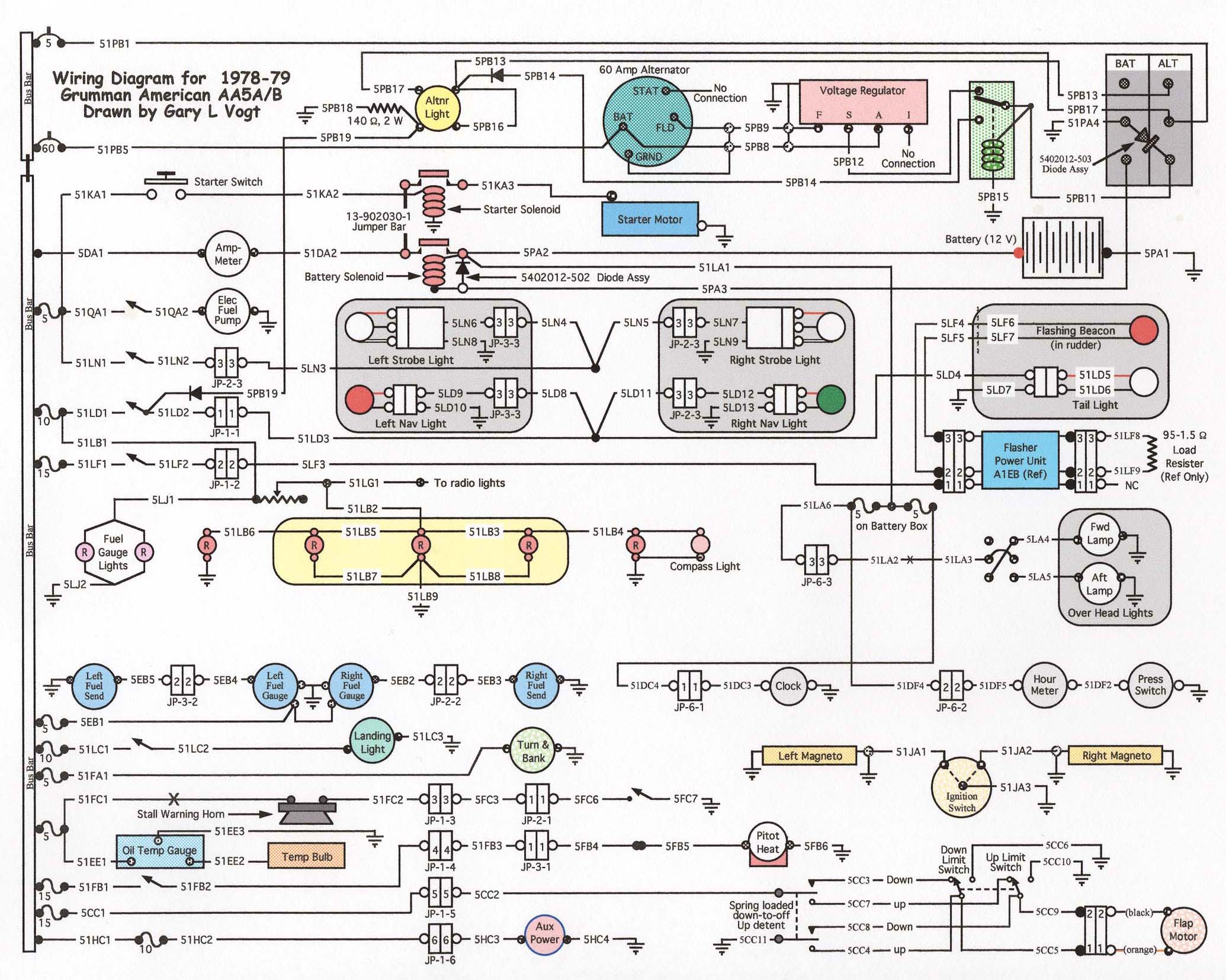
To help you know what wire goes where, the maintenance manual has detailed schematics. Gary Vogt has re-drawn the 76-77 and the 78-79 Tiger/Cheetah schematics in a little less technical detail.
All the troubleshooting described below is done with the engine OFF and the keys in your pocket.
Open the cowl and locate the voltage regulator. On Grumman American singles its on the passenger side just inboard of the motor mount attach point, directly above the battery. On AA-5x you'll see a connector on the bottom with several wires. Look closely and you'll see that they are marked with letters on the regulator. On AA-1x there are only 2 wires and they are crimped to the airframe wiring harness without any quick disconnects.
Visually check all of the wires and their crimped fittings. Pull gently on the crimped fittings, none of them should be loose. After 30+ years in service all these wires warrant close examination. Generally inspect the wires for large cracks in the insulation, or, where appropriate, the shielding. Look for breaks in the shielding pigtails.
Turn on the Master switch.
AA-5x series 12V
Locate the "S" terminal on the AA-5x regulator. Using your VOM, measure the voltage between the S terminal on the regulator and a good ground such as the battery's negative terminal. The VOM should read close to 12.6 volts on a fully charged battery. In this example, however, your battery is not fully charged after the in-flight failure of the charging system, so a measurement equal to 10 volts or greater is acceptable. If an acceptable voltage is present, then your Master Switch, Master Relay, Alt Field Circuit Breaker and the associated wiring are all working well enough to charge the battery from the alternator. Continue to the next step.
Locate the "F" terminal and measure the voltage just as you did at the "S" terminal. As before, if the measured voltage is within a couple of volts of the nominal battery voltage, then the regulator is correctly trying to "excite" the alternator field so that the alternator can produce an output. Continue to the next step.
Reset the VOM to measure resistance instead of voltage. Remove the "F" wire from the regulator and measure between the wire and ground. You should measure less than 10 ohms of resistance, and usually about 5 ohms. If you have significantly higher resistance (say 20 ohms or more) then there are problems with the alternator field or brushes, or possibly the wiring going to the alternator is in bad condition. A reading of less than 5 ohms, would indicate a short in the Field wire or inside the alternator. Otherwise, since you have the appropriate resistance between the "F" wire and ground, you are through checking the easy stuff, and are ready to pull the nose bowl.
AA-1x series
Locate the "I" terminal wire on the AA-1x regulator. Using your VOM, measure the voltage between the I wire on the regulator and a good ground such as the battery's negative terminal. The VOM should read close to 12.6 volts on a fully charged battery. In this example, however, your battery is not fully charged after the in-flight failure of the charging system, so a measurement equal to 10 volts or greater is acceptable. If an acceptable voltage is present, then your Master Switch, Master Relay, Alt Field Circuit Breaker and the associated wiring are all working well enough to charge the battery from the alternator. Continue to the next step.
Locate the "F" wire and measure the voltage just as you did at the "I" wire. As before, if the measured voltage is within a couple of volts of the nominal battery voltage, then the regulator is correctly trying to "excite" the alternator field so that the alternator can produce an output. Continue to the next step.
Reset the VOM to measure resistance instead of voltage. Disconnect the "F" wire from the regulator and measure between the wire and ground. You should measure less than 10 ohms of resistance, and usually about 5 ohms. If you have significantly higher resistance (say 20 ohms or more) then there are problems with the alternator field or brushes, or possibly the wiring going to the alternator is in bad condition. A reading of less than 5 ohms, would indicate a short in the Field wire or inside the alternator. Otherwise, since you have the appropriate resistance between the "F" wire and ground, you are through checking the easy stuff, and are ready to pull the nose bowl.
Turn OFF the Master at this time
We are through with the powered portion of the testing, so turn off the Master switch.
Right about now you are wishing that you had installed the split nose bowl STC, because without it you have to remove the propeller to gain access to the alternator.
Mechanical Difficulty: 
Up to this point, we were just CHECKING electrical measurements without any actual disassembly of the plane. If you do not have the split nose bowl STC, then this is the point at which you will require A&P supervision to complete the testing, removal and replacement of the alternator, prop, mounting bracket, etc. FAR 43 Appendix A paragraph (c)(19) permits the owner/pilot to remove and install cowlings without A&P supervision, if the prop does not have to be removed, after demonstrating the ability to do it correctly.
On all 2 place and on Travelers before 75, you can check the wiring by removing the screws on the right-hand lower cowling and letting the cowl side tip out from the firewall and nose bowl just enough to enable you to reach under the front cylinder and touch the wires on the back of the alternator. On 75 Travelers with the "Cheetah nose" and on all Cheetahs and Tigers, you have to remove the nose bowl to continue troubleshooting. That's OK, because you have already narrowed the source of the problem to that area anyway.
With the nose bowl off, or at least the lower nose off if you have the split nose, now remove the alternator belt from the pulley. Our testing so far has not ruled out a worn, loose, or missing alternator belt, so make certain that the belt is in good condition and properly tensioned.
The required amount of tension on this belt is often underestimated. The amount of power required to turn the alternator increases as the SQUARE of its output (charging) current! Lycoming's service information was updated a couple years back, and they now suggest setting belt tension by checking to see if the belt will slip before reaching a specified torque. You can check this by putting a socket on the alternator drive pulley nut and setting a torque wrench to 540 in-lb (45 ft-lb), and then holding the prop and trying to turn the alternator (CCW when viewing it from the front) with the torque wrench. The wrench should indicate 540 in-lb BEFORE the pulley slips. The older method mentioned in the Maintenance Manual, no longer favored by Lycoming, was to press in the center of the belt span between the pulleys and measure the deflection. New belts were to have less deflection than those that were worn. Refer to the maintenance manual if you don't have a torque wrench handy.
If the belt itself is in good condition and is tensioned correctly, the next step is to remove the alternator for inspection. First release the tension on the belt. To do this, cut the safety wire on the bolt holding the alternator to the bracket, then loosen the bolt enough so that you are able to push the alternator up, thus relieving the belt tension.
In the next step, you remove the alternator, which is quite heavy. If you have a portable service table or stand, now would be a good time to position it under the alternator. Now remove the big bolt at the bottom of the alternator (the one that holds it to the engine mounting bracket). While supporting the alternator so the wiring is not stressed, remove the bolt that was safety wired. The alternator should slide off the engine mounting bracket and be attached only by the wiring on the back.
Carefully turn the alternator around, and lift the rubber boot that hides the connection of the big wire to the back of the alternator. This is a VERY common failure point on the aging fleet. The wire breaks off the ring lug that is bolted down, and the alternator output is prevented from flowing back to the battery by the broken connection. Look also at the small wire that is bolted to the same connection. This is the "A" or sense wire which tells the Voltage Regulator what the alternator is doing. The sense wire is also a common failure point, though not as often as the larger output wire. Look at the other small wire which attaches to a different post. This is the "F" or field wire. If the resistance checks were normal earlier, then this wire should be fine; nevertheless, after 30+ years in service all these wires warrant close examination. Inspect the wires for cracks in the insulation, or, where appropriate, the shielding. Make sure the shield grounds at both ends of the F and A wires are in good condition and still connected, and check the sheilding pigtails behind the alternator, they can rub on the baffling and get worn through.
If there are no obvious failures in the wiring, you need to mark them and remove them so that the alternator can be tested at a shop. Pep-Boys and AutoZone will check your alternator for free. If you have an AA-5x series, then tell them its from a 71 Ford Pickup with AC. That is the actual original application for the Ford DOFF-10300J alternator on your Traveler/Cheetah/Tiger. AA-1x use a Prestolite brand alternator, and they should have no trouble figuring out the connections.
After the alternator is spun up and bench tested, all but the rarest and intermittent failures will have been diagnosed, and you will be repairing JUST the wiring, or replacing the alternator or the voltage regulator, and NOT spending money on needless repairs.
Prior to installing the alternator, carefully inspect the U shaped mounting bracket for cracks. They are prone to crack across the middle of the U, often into one of the bolt holes. Replacement brackets are available from any Lycoming distributor or from FletchAir.
Replacement Parts
If the alternator or regulator have failed, you may want to consider a modern replacement than have the old stuff overhauled. Honestly, for about the same price as an overhaul, you can have a new alternator. Plane Power makes a PMA'd alternator that is about 1 lb lighter, and they claim that it makes power at lower RPM. They also make a PMA'd modern solid state voltage regular. Zeftronics is also a popular solid state regulator replacement. If either the alternator or regulator has failed, have the other tested. In some cases, a failure in one of these causes problems in the other.